Dongguan Huayuan Electronic Technology Co., Ltd , https://www.zjsiliconefactory-oem.com
1 Overview
Mudanjiang No. 2 Power Plant is located in the northeast of Heilongjiang Province. The temperature difference between winter and summer can reach around 70°C. In order to ensure boiler ignition, stable combustion and safe operation with low load, there are a total of four 9000mmX9200mm above-ground open-air tanks in the fuel oil zone. For design reasons, residual oil has been used as fuel. The residual oil has the characteristics of large concentration, poor fluidity, many impurities, difficulty in dehydration, high flash point and high boiling point, so it must be preheated prior to combustion to utilize oil circulation and atomization. Due to the high oil temperature (up to 80°C), the return oil vapor in the oil tank is large. Especially in winter, the temperature difference between the inside and outside of the oil tank is large, and it is very difficult to measure the oil level.
Since the installation of the L2000 series radar level gauges provided by Dalian Ruida Automation Instrumentation Co., Ltd. in January 1999, it has solved oil level measurement problems under harsh environmental conditions in the North. After More than one year of operation, Satisfactory results. 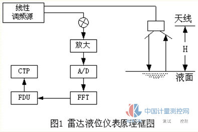
2 L2000 series radar level instrument working principle
The working principle of the L2000 series radar level gauge is shown in Figure 1. The high-frequency oscillating signal generated by the linear frequency modulation source in the LRG radar level gauge emits electromagnetic waves through the antenna. The electromagnetic wave encounters the liquid surface of the measured medium and is reflected back. After the emitted wave and the reflected wave are mixed, the difference frequency signal is obtained. This signal is related to the delay time I and corresponds to the distance H from the antenna to the liquid surface. After the difference frequency signal is amplified, A/D conversion, FFF and other calculations are performed, the level data signal is output, sent to the on-site FDU display, and sent to the long-range centralized processing unit CTP through the serial bus for display.
PDU field display unit consists of power supply module, display interface circuit, LCD module, etc. Its functional block diagram is shown in Figure 2. 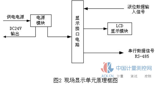
In FIG. 2, the interface circuit modulates and demodulates the liquid level data input signal and sends it to the LCD display module to display the liquid level value. At the same time, the liquid level signal is transformed into a strong anti-jamming capability, suitable for long-line transmission of Yang-485 serial data signals, and transmitted to a long-distance centralized processing unit CTP.
The LCD display module uses a 16 (character) x 2 (line) character module, which has the advantages of low power consumption, high reliability, and clear display.
The CTP centralized processing unit placed in a non-hazardous location, according to its different models, provide different working modes: One is to convert the serial RS-485 signal transmitted from the FDU field display unit to RS-232C signal and calculation The grid connection, as shown in Figure 3. The other is to export the transformed 4-20mA current signal, which is connected with the user's own display header. 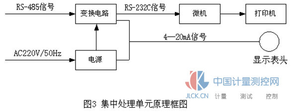
L2000 series radar level instrument consists of three parts: LRG radar level gauge, FDU field display unit, CTP centralized processing unit.
(1) LRG Radar Level Gauge
The radar level gauge is a radar level instrument detector whose role is to obtain the level data. The outline of the UlC radar level gauge is shown in Figure 4, which includes host and antenna feedback system devices. 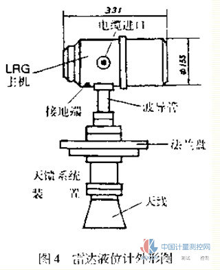
The radar level gauge is installed on the top of the tank and has explosion-proof performance. It can be divided into two kinds according to different antennas: one is air transmission type, and the other is transmission type of waveguide.
The advantage of the waveguide transmission radar level gauge is that the liquid level in the tube is relatively stable, can achieve high detection accuracy, and can avoid all kinds of random reflection interference in the tank. It is particularly suitable for the relatively narrow space in the tank or the instrument installation position from the tank. Wall too close. The oil level measurement of the open-air oil tank of our factory adopts a waveguide transmission radar level gauge.
(2) The function of the FDU field display unit field display unit is to convert the signal of the LRG radar level gauge on the tank top into RS-485 serial data signal and send it to the centralized processing unit, and provide the user to observe the liquid level value under the tank. Convenience. In addition, the FDU field display unit can convert the AC220V power supply to DC24V to supply the LRG radar level gauge; the magnet can be used to set the parameters of the LRG on the glass dial; it can also be used as the temperature, pressure and other process parameters in the tank. Transmission channel. 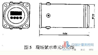
The on-site display unit can be installed in the lower part of the tank or in the on-site working room according to the user's needs. The FDU field display unit installed under the tank is shown in Figure 5. Because it is installed in dangerous places, it also has explosion-proof performance.
(3) CTP centralized processing unit
The role of the centralized processing unit is to display and alarm the level data. It also has many types, one of which has a character display processing function, and a CTP centralized processing unit that can display the liquid level values ​​of 1 to 8 tanks, respectively, is shown in FIG. 6 . For the CTPs with different display processing functions, the external structure is different.
The CTP centralized processing units are all installed in the safe area, and are connected to the user's own matched machine or display meter through cables. 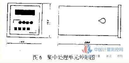
4 system configuration
There are four vault storage tanks in the fuel oil area, and a centralized processing unit CTP2001 can accept 1-8 oil level signals. Therefore, a CTP2001 can be used for indoor instrumentation. The system configuration is shown in Figure 7. 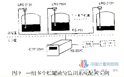
If necessary, the FDU field display unit can also be installed under the tank so that data can be observed and parameters can be set without boarding the tank top.
5 Instrument installation
Because the meter measuring port on the oil tank of our oil tank is only 0.7 meters away from the tank wall; therefore, an air-transporting radar level gauge cannot be used and a waveguide-type radar level gauge can be applied. Installation diagram such as 8. 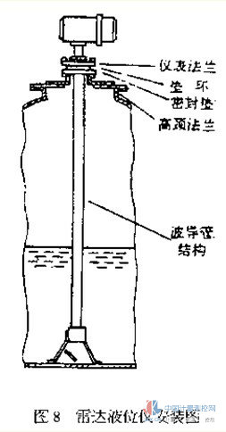
According to the properties of residual oil, we improved the design of the waveguide structure, and increased the size of the flow hole as appropriate to achieve better results.
In addition, because of the high oil temperature, in order to ensure the safety of the instrument, we use the thermal ring isolation method.
6 Operational conclusions
The system has been operating since January 1999. The meters are operating normally and maintenance-free. Workers no longer use outdoor readings and can directly extract data from the control room. This provides remote monitoring for the fuel oil area and lays the foundation for unattended operations. The advantages of this meter are:
1. Operating in the North, the ambient temperature is -35 °C to + 35 °C; wind is often above the 6th level, the instrument survived the environmental test.
2. The measured medium is residue, which is characterized by viscous, very poor fluidity, medium temperature above 80 °C, large concentration of oil vapor, the instrument lived through the media test. It can operate normally for a long period of time under conditions of harsh environments and wide temperature variation.
3. The instrument has strong anti-interference ability, high precision (less than 5mm), good stability, reliable window, and maintenance-free. It is particularly suitable for applications in harsh environments, with broad application prospects and promotion value.
Through one year of practice, we have increased confidence in the use of radar level instruments in power plants in cold northern regions.
Application of L2000 Series Radar Level Gauge
Abstract: Since Mudanjiang No. 2 Power Plant has been put into production, it has been using residual oil, the residue from petroleum refining, as fuel. Because the residual oil level is difficult to measure and control, it poses a serious threat to stable combustion and low-load safe operation of the boiler. Since the installation of the L2000 series non-contact radar level gauges provided by Dalian Ruida Automation Instrumentation Co., Ltd., an on-line continuous oil tank in the fuel oil area has been realized. 3 System Composition